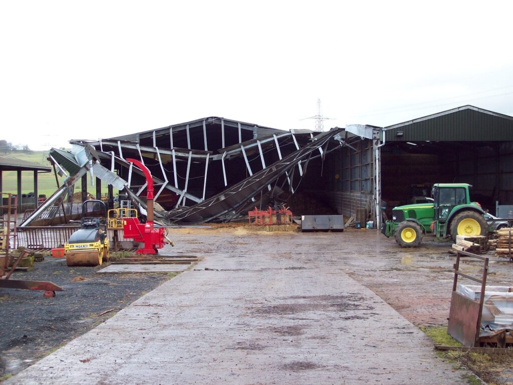
Photovoltaic (PV) panels are becoming an increasingly common sight on buildings across the UK, as owners attempt to turn sunlight into cash while doing ‘their bit’ for the environment. Farm buildings are no exception, especially where electricity is required to power plant and processes within the building. If, however, the PVs are not installed correctly, taking proper account of the type and condition of the roof, their installation can lead to potential problems over their service life. Retrofitting PVs onto existing roofs can be especially problematic if the original roof and supporting structure were not designed for the additional loading.
This article assumes that the roof cladding is made from steel or aluminium sheet, since these materials provide the best support for the PVs and allow indefinite safe access for future maintenance. PVs may be installed on fibre cement roofs, but in this case, the panels should be supported by a frame erected above the roof cladding to avoid loading the cladding itself.
Types of PV
PV installations on roofs may be divided into 3 types:
- Inclined roof mounted
- In-plane roof mounted
- Roof-integrated.
Inclined roof mounted PVs are commonly used on flat or low pitch roofs and allow the panels to be supported at the optimum angle for receiving solar energy irrespective of the roof pitch. They comprise PV modules laminated onto carrier panels, which are in turn supported by a framing system. The frame system may be anchored through the roof directly to the purlins to resist wind uplift, or attached to the roof sheets. Some systems use ballast to resist wind uplift, so do not require penetrations. The downward forces are transmitted to the roof via pads, which are generally shaped to suit the cladding profile. The frames may be installed parallel to the length of the building, or twisted through a few degrees on plan, to point as close to south as the building allows. The primary disadvantage of inclined roof mounted PVs is the weight of the system, which is typically in the region of 20 kg/m2. Given that single skin steel cladding (0.7mm gauge) only weighs 7 kg/m2, it is apparent that the PV adds considerably to the dead load on the roof structure. Where ballast is used to resist uplift, the weight of the system can be as high as 35 kg/m2.
In-plane roof mounted PVs are probably the most common in use on agricultural buildings. As the name suggests, the PV modules are installed in the plane of the roof slope, so do not require an additional framed structure. An obvious disadvantage is that the inclination of the panels is fixed to the pitch of the roof. However, since agricultural buildings typically have roof slopes between 15 and 25 degrees, this is less of a problem than on industrial buildings. On the positive side, in-plane systems are relatively lightweight, typically < 10 kg/m2 and are suitable for installation on either existing or new roof structures.
There are numerous systems available in the UK, each with its own advantages and disadvantages. Options include:
- PV trays with clipped connections – ideal for use with standing seam roofs
- PV trays with adhesive bonded connections – ideal for use with trapezoidal profiles
- PV strips (narrow trays) – designed to suit the cladding profile.
The first two options are designed to run across the ribs of the cladding profile, so are often installed in long strips running along the length of the building. By contrast, the narrow strips are designed to run down the roof slope. An additional advantage of the clipped tray is that the whole PV panel can be removed in the case of damage and replaced without damaging the roof sheeting.
Roof-integrated PVs comprise PV modules that are integrated with the roof cladding in the factory and then installed on site as part of the building envelope. This type of system is mainly suitable for use on standing seam roofs, so is rarely used in agricultural applications. A typical roof-integrated solution comprises flexible thin-film PV laminates adhesively bonded to the pan of a standing seam cladding system. The laminates are very lightweight, giving a total system weight of only 7 kg/m2 including the weight of the cladding sheet. Furthermore, no penetration of the roof skin is required and there are no implications for the building structure. On the down side, in the event of laminate damage, the whole standing seam sheet needs to be replaced, since the laminate cannot be detached from the cladding.

Loading on PVs
When designing a building to support a PV array, the structural engineer needs to consider the implications for the loading on the building structure. There are 4 issues to consider:
- Additional dead loading due to the weight of the PV system
- The need for access to maintain the panels
- The impact on wind loading
- The potential for snow drift.
The additional dead load will depend on the type of PV system as noted above. Where inclined roof mounted systems are used, the weight of the frames and panels is likely to have an impact on the design of the building structure. This is unlikely to be the case for the in-plane systems. The structural engineer should also consider the impact on downslope roof loads and ensure that the panels cannot slide down the roof. There are no specific requirements given in BS 5502-22 in terms of access loading for PV maintenance, but it is probably wise to use 0.6 kN/m2 (as used on industrial buildings) rather than the 0.4 kN/m2 allowed on some agricultural buildings.
The wind loading will also depend on the type of PV system. For roof-integrated PVs, the wind loads will be identical to those on a conventional building, since the PV is part of the envelope. In-plane roof-mounted panels experience wind uplift due to wind acting directly on the roof surface, as well as potential uplift due to the offset between the panel and the roof sheeting. This offset creates a void, resulting in an additional internal pressure component. BRE Digest 489 provides guidance on this issue. Inclined panels require special wind load calculations due to the action of the wind as it blows over the panels (analogous to installing a wing on the roof). BRE Digest 489 also provides guidance on this type of panel.
In Service Issues
When considering the installation of PV panels on the roof of a new or existing building, the following issues need to be considered:
- Access for maintenance
- Durability of the envelope
- Ease of replacement.
The installation of PV panels will inevitably increase the requirement for maintenance access with consequential implications for health and safety. Designers must ensure that the roof cladding and supporting structure are suitable for this purpose. Special attention should be given to the non-fragility of the roof (minimising the risk of falling through the roof), walkability (minimising the risk of damage) and fall protection (minimising the risk of falling off the roof). The first two issues may be addressed by specifying steel cladding of an appropriate gauge and profile (and fixing it correctly).
PV panels provide a trap for dirt and debris, which can accumulate to the detriment of the cladding panels. The lack of natural airflow and rainwater washing will both contribute to this problem. If the dirt contains corrosive salts, these can have a negative impact on the durability of the cladding, especially in coastal or industrial environments. Good maintenance is therefore essential.
It is quite likely that the PV panels will fail many years before the cladding has reached the end of its life. Building owners, therefore, need to consider how they will replace the panels without needing to replace the whole roof.
Conclusions
The use of photovoltaic panels on the roofs of agricultural buildings provides a means for farmers to meet some their energy demand while having a positive impact on the environment. Modern agricultural buildings designed by a professional structural engineer with profiled steel roof cladding provide an ideal base for PV arrays, provided that sufficient attention is paid to the design of the building to meet the additional loads and that an adequate provision is made for future maintenance.