RIDBA office Christmas closure

Lamma-pic

Thank you for supporting RIDBA in 2022.

The RIDBA office will be closed for Christmas from midday on Thursday, December 22 until 9am on Tuesday, January 3.

We hope you find some time over the festive period to wind down with family and friends and prepare for what is sure to be a busy 2023.

It will certainly be a busy start for us! Just one week after our return we will be sharing the exhibition floor with hundreds of exhibitors at LAMMA.

We’re looking forward to welcoming visitors to the RIDBA stand (8.938 – hall 8) to explain what the association does and the benefits of using a RIDBA member.

Click here to register.

Historic city revealed as host of RIDBA Building Awards

Graduate_Cambridge_River

Hundreds will head to Cambridge next September for the return of RIDBA’s flagship event.

It’s been confirmed the RIDBA Building Awards will take place at the Graduate Cambridge hotel, nestled on the banks of the River Cam.

The biennial event celebrates excellence in the modern agriculture and industrial buildings industry and will take place on Friday, September 22, 2023. Click here to see the winning projects from the RIDBA Building Awards 2021.

Neil Fox, RIDBA chairman, said: “I’m really looking forward to the return of the Building Awards. We have a fantastic venue lined-up which I’m sure RIDBA members will enjoy, and I’m always amazed by the quality of the entries.”

“I’d encourage all members to enter. To win – or even be shortlisted – is a fantastic achievement, and it’s a great way of showcasing your hard work and achievements to the rest of the industry.”

“It was a fantastic event in 2021 and we can’t wait to see everyone in Cambridge next September.”

A total of eight prizes will be up for grabs:

  • Residential and offices award
  • Livestock award
  • Farm storage award
  • Commercial award
  • Industrial and production award
  • Training award
  • Outstanding workmanship award
  • Most effective product and/or service award

The 2023 event will be open exclusively to RIDBA members and suppliers, architects and specifiers working on projects completed between December 1, 2021 and March 31, 2023.

Entries will open on December 1, 2022, and close on March 31, 2023.

  • Click here to book your tickets for the event.
  • Click here to book a hotel room at the Graduate Cambridge.
  • Click here to see sponsorship opportunities at the RIDBA Building Awards 2023.

Heat and moisture: Predictable design issues

Jamie-1

“In hot conditions, cattle can become unproductive, overheat or die”.

Those words are from the opening line of a paper in the Journal of Agricultural Engineering Research published in 2000 by two colleagues – Rod McGovern and Jim Bruce. They had produced a model of the thermal balance for cattle in hot conditions and concluded that in hotter conditions, feed intake would be reduced, and production would fall.

Since then, we have also come to understand that there is an earlier negative impact of hotter conditions/heat stress. Namely, that is the reduction in fertility (RIDBA Journal 2021: Vol 22, Edition 1). Their thermal model included air temperature, humidity, wind speed and radiation, together with metabolic heat production from the animal.

Metabolic heat is lost from the body in a variety of ways. They include conduction from the body core to the skin, from the skin by convection, by long-wave heat transfer by radiation, and by latent heat loss via respiration and sweating.

Table 1 shows the results of instantaneous heat balance simulations at four different air temperatures.

Example 1 2 3 4
Air temperature oC -10 15 30 40
Heat production W/m2 122 122 122 80
Respiratory heat W/m2 47 12 74 73
Stored heat  W/m2 0 0 0 83.5
Evaporation from skin W/m2 17 142 116 (max) 181 (max)
Convective heat loss W/m2 15 59 45 28
Heat flux through coat W/m2 102 11 -24 -75
Respiration rate, breaths per minute 12 12 59 86 (max)
Rise in body temperature oC 0 0 0 1.2
Table 1. Results of instantaneous heat balance simulations

Solar radiation can be added to the model to give results for the expected impact of solar gain (or shading) delivered at stated angles, wind speed, cloud cover, latitude, albedo, the emissivity of the animal and the reflectance. Many of these terms will be familiar to building engineers, but what is the result?

In cold weather – example 1 in Table 1 – convective heat losses are reduced by vasoconstriction but losses through the hair coat are high. In example 3, respiration rate increases to dump more energy as moisture and in example 4 the body starts to acquire heat and body temperature rises. In reality these cattle will already have adapted but with resultant losses to fertility, then feed intake, and then milk production.  The impact of the summer which we’ve just experience in the UK on cattle was, and is, predictable.

The daily – or diurnal – pattern of air temperature can lead to a predictable pattern of heat stress in livestock, and a more recent study with young calves at Iowa State University (Appuhamy, et al. 2021 “The Effects of Diurnal Heat Stress in Dairy Heifer Calves”) describe further impacts.

The study shows that although feed intake increased at night to balance the reduced feed intake during the heat of the day, average daily liveweight gain and feed efficiency decreased significantly during periods of diurnal heat stress. They considered these effects are a likely consequence of nutrients being moved towards an activated immune system and away from productive processes. They also report that water intake per unit of feed consumed also increased significantly during diurnal heat stress.

We do need the science to inform us, and we don’t need the science to inform us. When it gets hot animals consume less food and drink more water and may have reduced immune competence. What a surprise! But heat and water are issues that have been tackled with different levels of precision around the world and this summer will have shaken UK livestock producers – hopefully into an acceptance that what is predictable can also be managed better. We have plenty of information on how to better manage heat and water in the UK’s livestock buildings, but we need to acknowledge the issues first, and work out what it costs to get it wrong.

A recent query involving a new build pig unit threw up the interesting detail that for the month of July 2022 the water consumption in the farrowing rooms increased by 20 litres per pig, per day, compared with the average of the previous three months. That is 37 m3 for the month on this particular site – from drinking water intake increasing to the smart pigs throwing water everywhere to keep cool. Of course, this also adds to slurry volumes. Dairy cows dramatically increase the volume of water intake in warm weather and pigs and poultry show clear preference for cooler drinking water in hot weather conditions. The main production and design questions for any farm – new or existing – are:

  • Do we have the correct volumes and flow rates of decent water quality and temperature at the right height and with adequate space for expected competition?

That is no less than six design factors to get right, or wrong.

In food production processes, heat and moisture go hand in hand and the UK agricultural sector has plenty of potential to improve on the management of both factors. Potential gains have been mentioned before as something that need to go into any investment appraisal of our livestock systems. The example of poor fertility – the major reason for culling cows in the UK (NADIS 2022) – will be uppermost in UK dairy statistics this year of high air temperatures and low rainfall. The financial losses of poor fertility accrue from a range of variables (Table 2) and average £250 per cow in the UK herd.

Table 2. The cost of poor fertility.

  • genetic gain
  • milk production
  • veterinary costs
  • number of heifers that need to be reared
  • cost of AI (or the number of bulls needed)
  • Disrupts the pattern of milk production

The chronic health issues linked in part to climate extremes are costing tens of thousands of pounds every year on individual UK livestock farms, which leads to significant potential benefits to offset investment in improved building design and higher specification materials.

And sell rainwater harvesting to the clients and the planners! It should be good business sense and will improve the sustainability image of our industry.

Jamie Robertson
RIDBA Livestock Consultant

Members enjoy factory tour

Shufflebottom_Head_Office

RIDBA members were greeted with open arms during a visit to their fellow member Shufflebottom earlier this month.

Director Alex Shufflebottom gave an insightful talk on the history of the Llanelli-based and spoke about its recent investments in its production process and people.

Following the talk, a tour of the factory took place before the group held a discussion on the current challenges facing the industry such as labour and costs.

The group of nearly 20 attendees then enjoyed a meal at a nearby restaurant.

RIDBA general manager Joe Chalk said: “Thank you Alex for hosting the day and to the whole Shufflebottom team for being so welcoming and taking the time to talk us through their roles.

“Thank you too to Clive Mander for his help with the preparations.

“It was great to see so many members make the journey to Llanelli – the feedback we’ve had on the day has been really good and will prove useful when it comes to planning future RIDBA events.”

Bookings for ‘fascinating’ tour of factory set to close

07-Shufflebottom-Logo-Page-19

RIDBA members are running out of time to book their spot on a tour of the factory of Shufflebottom.

Shufflebottom is an award-winning company which specialises in steel-framed buildings and structural steelwork and has built more than 15,000 structures across the UK.

The RIDBA member was established in 1986 with the second generation of Shufflebottom’s – Alex and Wesley – becoming directors in 2008, alongside general manager Alec Davies.

Alex Shufflebottom said: “We’re looking forward to welcoming members to our base in Llanneli. Following an introduction to the company’s history, we’ll be taking members through each stage of our manufacturing process.”

The tour will begin at 3pm on Thursday, September 8 and will be followed by a meal at The Plough, in Llandeilo, a short drive from Shufflebottom.

Joe Chalk, RIDBA general manager, said: “My thanks to Alex and the team at Shufflebottom for agreeing to host a tour. I’m sure it will be a fascinating visit and a fantastic opportunity for members to catch up!”

Bookings close on Thursday, September 2. RIDBA members can secure their places by emailing [email protected].

Designing buildings to withstand winter storms: Part II

Page-8-scaled

In the previous issue of the RIDBA Journal I wrote about wind loading on buildings and how to design with it in mind.

The article considered the many factors that affect the speed of the wind as it approaches a building, or other obstruction, and the need to perform bespoke wind loading calculations for each building. The article also referred to the Eurocode standard for wind loading – BS EN 1991-1-4 – and the availability of wind loading software. In this second article, the focus switches from the wind to the buildings and considers how the structural frame, cladding and attachments can be designed to withstand the winter storms.    

The structural frame

All structures, including buildings, must be designed with sufficient stability to withstand horizontal forces, such as wind loading, without collapse or excessive deflection. The means of providing this stability will depend on the type of building and any constraints placed on the structure by the building use. For example, the need for a clear opening without bracing. Resistance to horizontal forces is generally achieved through one of the following methods:

  • Bracing system
  • Concrete core or shear wall
  • Moment-resisting connections  

Of these options, the use of a bracing system is probably the most common in multi-storey buildings or in single storey buildings where large clear openings are not required. Cores and shear walls tend to be used in tall buildings where bracing would be obtrusive and where a service core already exists for the lifts and a stairwell. Moment-resisting connections are used where clear openings are needed in buildings and where a core or shear wall would be impractical, such as warehouses and agricultural buildings. Portal framed buildings typically combine two means of stability. In the plane of the portal frames, wind loading is resisted by the hunched connections between the columns and the rafters, while bracing in the walls provides the resistance out of plane. 

It is worth emphasising that the bracing system, where it is used, is as important as any of the other structural members in the frame. Bracing members are not optional extras that farmers can remove to make a side entrance to their cow shed.  If a bracing member needs to be moved, a qualified structural engineer should be consulted to ensure that an alternative means of stability is provided.

The bracing and haunches prevent the building from collapsing sideways, but what about the whole building overturning or lifting off the ground? This is the job of the column bases and their holding down bolts, although from the way they are often treated on site, one could be mistaken into thinking they are little more than ornamental features.

A typical column base consists of a steel plate, known as the base plate, welded to the base of the column, and connected to the concrete foundation by four holding down bolts. Although two holding down bolts are likely to be adequate to resist the design loads, four should always be used for the sake of safety during erection. When the wind blows on the side of the building, it simultaneously attempts to move the building sideways and overturn it. This overturning moment is resisted by a downward reaction on one set of columns and an upward reaction on the other side of the frames. Consequently, column bases need to be designed to carry upward and downward vertical loads in additional to horizontal base shear.

Downward vertical loads are taken directly into the ground in compression, with the base plate spreading the load to limit the pressure on the concrete foundation. Vertical uplift loading is taken in tension through the columns into the holding down bolts and is ultimately resisted by friction between the foundation and the surrounding soil. Horizontal loads are taken into the foundations by the bolts acting in shear. The holding down bolts should be specified to resist the uplift on the column base in tension and to transfer the horizontal forces in shear. The size of bolt will depend on the magnitude of these forces, but M20 is typical for small and medium size sheds. Remember that any column base is only as good as the foundation to which it is attached, so take great care to ensure the foundations are adequate to hold the building down in the event of a storm.

The final structural issue to consider is the impact of wind uplift on portal frame rafters, which in some cases can be the dominant design condition. Moreover, due to their slenderness, the rafters are usually susceptible to lateral-torsional buckling and have to be restrained at regular intervals along their length. Under downward loading (e.g., self-weight and snow), the critical compression flange is mostly at the top of the rafter (it is at the bottom close to the haunch), so is directly restrained by the purlins. Under wind uplift, however, the opposite is true and, unless correctly detailed, the compression flange will be unrestrained and at risk of buckling.

The building envelope

So far, this article has only considered the impact of the wind on the building structure, but quite often it is the building envelope and decorative elements such as fins, awnings and signs that bear the brunt of any storm. While these items are not normally classed as structural, i.e. their failure will not result in the collapse of the building, they are often essential to the serviceability of the building and their detachment from the building can be extremely dangerous (think of thin metal sheets flying through the air). Designing the roof, wall cladding and any attachments for the appropriate wind loading is therefore as important as designing the structural frame.

Building designers will often assume that the wind loading is shared across the whole building when designing the structure, but this approach is not valid when it comes to the building envelope due to the significance of local wind forces. Although it is reasonable to assume that the wind blowing towards a building is uniform, once it reaches the building and begins to flow over and around it, the wind pressures can vary enormously from one location to another. This variation in wind pressures is dealt with in the design codes using ‘wind zones’.

Large signs, light fittings and any other wall-mounted attachments require special consideration, since the wind force will need to be taken into the cladding and then back into the structure.  This poses two potential problems. Firstly, the bracket or rail system supporting the attachment must be strong enough to safely transmit the wind load, which in some cases could be significant. Secondly, where these brackets attach to the cladding system, there will be a concentrated local force on the cladding. If the connection is not detailed correctly, this could result in local failure of the cladding.  It is always advisable to contact the cladding manufacturer for specialist technical guidance in these circumstances. 

Conclusion

Storms can release great destructive power, which all too frequently causes damage to buildings. This is, however, largely avoidable if building designers take the time to calculate the wind loading on the building and correctly detail the structure and envelope to ensure that the structure is adequately braced and held down and that the cladding is securely fastened to the structure.

Dr Martin Heywood
RIDBA Technical Consultant

Investment in new infrastructure must account for balancing act between cost and value

JR1

The interaction of space and animal welfare has been mentioned before in this section, along with the suggestion that we need to recognise the value of the quality and quantity of space made available to animals.

In the early days of research into animal welfare and the development of animal systems, the defining physical attributes were space (m2) per animal, ambient temperature and not a lot more.

The optimum number of animals in a group (cows can “recognise” up to 60 cohorts, not more) or the height of water troughs and feeders was evaluated (depending on age), and as the science improved the design of animal systems also included factors such as air changes per hour (based on CO2 production) and the design of sleeping areas (lunge space; cubicle design).

Overall, there emerges an understanding that while we can easily define an equitable unit of space per animal, there is considerable value in the quality of that space, but the quality will often come at a cost. So, the question for the system designer is how much-increased cost does the client value?

The UK cattle sector is the same as any other business in that it needs to invest to remain sustainable, and once the ear tags, fancy feed additives, power, water and all the other consumables have been paid for, there is a need to invest in buildings.

They represent a major, once-in-a-lifetime cost, but the aim is to bring value to the business. The build design process needs to start with the number and size of animals to be housed, group size and feed system. Immediately there will be conflict because the industry experience is “we can/cannot keep 10/15/20 cattle per bay” and “we have always done it like this” and “We tried one of those and it did/didn’t work“. It is not logical to make a once-in-a-lifetime series of technical decisions based on a string of opinions. Instead, refer to the information provided by BS5502 and the RIDBA Farm Buildings Handbook or AHDB guidance material.

The Dairy Housing: A Best Practice Guide (AHDB, 2012) outlines the space requirements in cubicle housing. The book has been freely available for more than ten years and yet producers and builders will still build cattle housing that does not fit industry guidance or – the usual favourite – only use the guidance information they want. The aim is to house a certain number of cattle at a cost and not at a value. We know that wider passageways, cubicles, feed and water spaces, cross-over passages and holes in the roof all increase the cost per cow, and we need to sell the value of these increased costs.

The benefits of good design outlined in the AHDB Dairy Housing booklet include:

  • Longer lying times
  • Better feet condition
  • Reduced aggressive behaviours
  • Reduced fouling
  • Reduced risk of udder damage or disease
  • Optimised feed and water intake
  • Improved bedding conditions
  • Reduced slurry pooling
  • Reduced heat and cold stress

In addition to the above, improved fertility with adequate floor space and surface, lighting quality and impact of well-designed ventilation on the incidence and severity of respiratory diseases, also apply. The positive value of the cost of these design features on the lifetime of a building will run into the tens of thousands of pounds.

Provision of a large area building for single animal systems can be attractive as a means of restraining build costs per housed animal. Build costs per unit of space can be reduced as the total build space increases, up to a limit.

Builders need to be aware the engineering limits on a single build space are far higher than animal system limits on space. This has been mentioned previously whereby an increased number of animals in a single airspace increases the risk of the spread of disease. The poultry sector and, to a lesser extent the pig sector, manage this by designing buildings that match the throughput of animals to facilitate All IN, ALL OUT (AIAO) management of each room. 

The image below shows a beef new build on a top-class farm where there will need to be a significant change in health management before next year to avoid repeat health issues from this past season. The build design and quality is fine, but because the build area is so large that it contains stock of mixed ages, the space quality has been reduced compared with building two separate air spaces. Space cost versus space value.

Jamie Robertson
RIDBA Livestock Consultant

UKCA webinar arranged exclusively for RIDBA members

BM-Trada

Following requests from RIDBA members, certification experts BM Trada will deliver a webinar on UKCA marking and the changes you need to be aware of prior to implementation in January 2023.

This online event will take place on July 5 via Zoom. RIDBA members can register for free here.

UKCA (UK Conformity Assessed) marking is a new UK product marking that is used for goods being placed on the market in Great Britain (England, Wales and Scotland).

The UKCA mark was introduced on January 1, 2021, however, to allow businesses time to adjust to the new requirements, CE marking can be used in most cases until December 31, 2022.

Once the webinar has finished, there will be a short Q&A session.

Ahead of the webinar, RIDBA will host an EGM to adopt its new code of practice.

As part of RIDBA’s development, the Board has undertaken a review of its code of practice to ensure it reflects where the association is today, and so members are aware of expected standards.

Notice of the EGM and a draft copy of the new code of practice will be distributed to members on June 14.

Designing buildings to withstand winter storms

Page-8-scaled

My intention for this article was to present an update from the various British Standards committees on which I represent the interests of the agricultural sector.

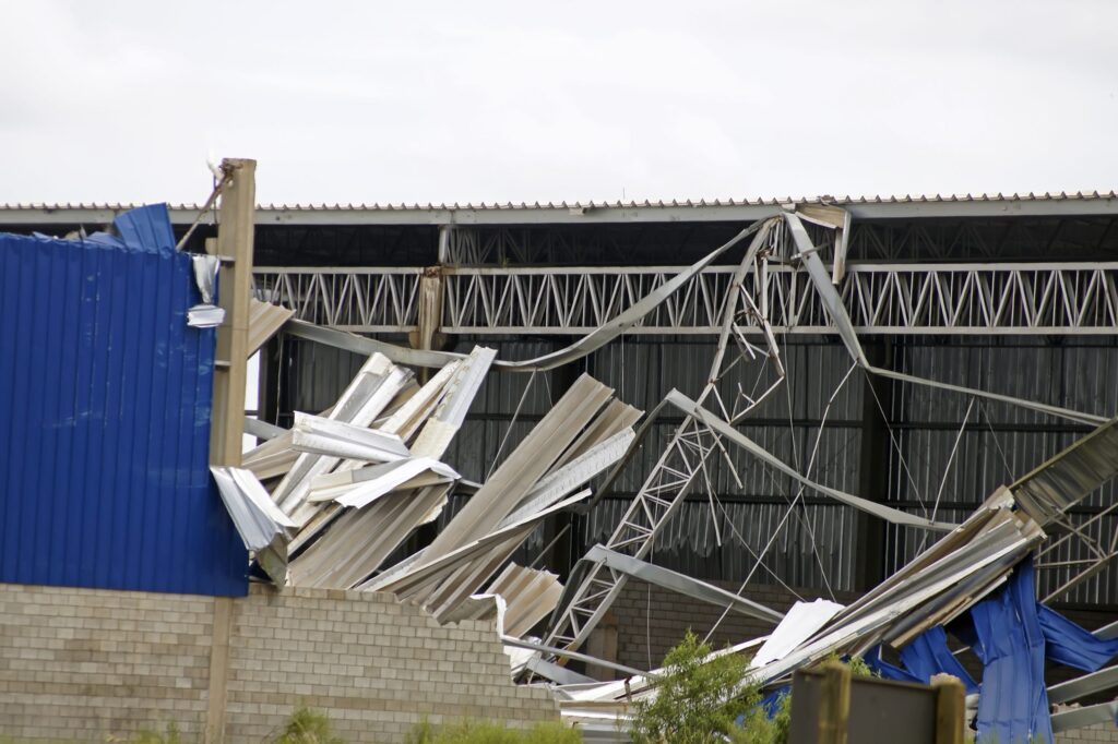
Then the Met Office issued a rare red weather warning and Storm Eunice arrived. Once again, the news was filled with fallen trees, displaced trampolines and cladding (roof and wall) ripped from modern buildings.

While the first two can be regarded as the expected norm when storms and gales hit our country, the sight of cladding sheets and panels flying around left me wondering whether the UK had just experienced the one-in-50-year event that buildings are supposed to be designed for, or whether some buildings had not been designed properly.

With this in mind, this article revisits the issue of wind loading on buildings and explains how buildings can be designed to withstand the worst of our winter storms. In the next issue, I shall look specifically at some of the detailing issues that affect the storm resistance of buildings.

Wind forces on buildings

Let’s start with some basic aerodynamics. When the wind blows over or around a building, it is forced to change direction and either speed up or slow down depending on the shape and orientation of the obstruction.

Where the wind blows directly onto a surface, the local external pressure will increase. Where the wind blows parallel to a wall or over a roof, it speeds up causing a decrease in the external air pressure. Unless the building is completely airtight, the wind will also change the internal pressure, either increasing or decreasing it.

The combination of changes to the internal and external air pressure results in either a net positive pressure (on windward facing walls, and the windward slopes of steep roofs) or a net suction (on leeward facing walls, on walls parallel to the direction of the wind and on roofs generally).

From a building design point of view, it is important to understand that wind speed varies enormously with location and building geometry, meaning wind loading is site and building specific, so should be calculated for each and every building project.

Since the magnitude of the wind loading has a direct bearing on the design of the frame, column and rafter sizes for example, it follows that the design of every building is. It should come as no surprise that a building designed for a sheltered location in Oxfordshire may not be adequate if placed on a hilltop on the coast of Cornwall.

Importantly, the wind force on the building is proportional to the square of the wind speed, so doubling the wind speed will produce four times the wind loading on the building.

What are the factors that affect wind speed

1. Location

Some parts of the country tend to experience higher wind speeds than others and this needs to be taken into account when calculating the wind loading on a building.

To enable engineers without specialist meteorological expertise to judge the likely wind speed at a particular location, the available meteorological data has been analysed to produce a contoured wind map of the UK, which is published as part of the UK National Annex to BS EN 1991-1-4. The values shown on the map are magnitudes of the basic wind speed to which correction factors may be applied to take account of wind direction, altitude and exposure conditions.

2. Altitude

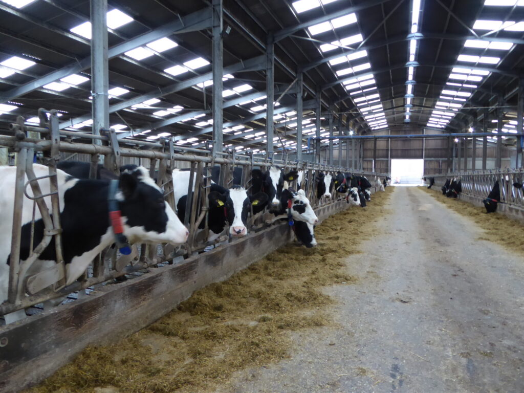
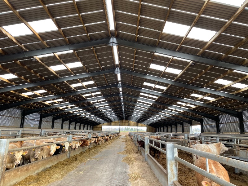
Wind speed increases with altitude and this is accounted for by a correction factor that is applied to the basic wind speed. This is especially important for agricultural buildings, since many are constructed at altitudes higher than 200m above sea level, where wind speeds are significantly higher than those in low-lying locations.

3. Distance to sea

The shorter the distance to the sea, the greater the wind speed because the wind loses energy and speed as it blows across land. The greatest reduction in wind speed occurs over the first few miles, meaning that locations on the coast experience much higher wind loading than sites only one or two miles inland. Cliff top sites that combine a coastal location with altitude, experience particularly high wind speeds.

4. Town or country

Agricultural buildings are generally built-in exposed locations that do not benefit from the shelter provided by a surrounding town or city. This results in wind speeds which would be higher than would be experienced by comparable buildings located on an urban site.   

5. Topography

Topographical features such as hills can increase wind speed as the air is forced over them. For this reason, it is important for the person calculating the wind loading to have some familiarity with the site and not simply rely on postcodes. Local obstructions can have a significant impact on the wind speed, by providing shelter, for example, but this effect may vary across the site or even across the building footprint.

6. Wind direction

In the UK, the strongest winds generally blow from the southwest, so a southwest facing coastal location is likely to experience stronger winds that one on the North Sea coast. As wind can – and does – blow from any direction, the factors listed above, in particular distance to the sea and distance into a town, need to be assessed for several points around the compass and the wind speed calculated for each direction.

7. Building height

Taller buildings are exposed to stronger winds and this needs to be reflected in the wind loading calculations. For single storey buildings it is common practice to calculate the wind speed for the ridge height. For a multi-storey building, especially high rises, it is possible to divide the building into zones over its height, so that only the very top of the building is designed for the maximum wind loading.

Design practice

The wind forces acting on a building should be calculated using a recognised code of practice, which in the UK is BS EN 1991-1-4. This is one of the structural Eurocodes and is applicable across Europe, although each country has its own National Annex containing nationally determined parameters and specific national recommendations.

The calculation method in BS EN 1991-1-4 is complex and requires specialist technical knowledge, so it is essential wind loading calculations are undertaken by a qualified structural or civil engineer.

By far the simplest approach is to use one of the many software tools currently available. These range from commercially available packages that take account of all of the factors noted above to free online tools that produce reasonable, but conservative, results with minimal input from the user.

Several steel purlin manufacturers include wind loading tools as part of their specification software which are free to customers. In many cases, the precise site location may be specified in the software by its postcode or grid reference. Alternatively, various online resources may be used to obtain the grid reference, altitude and other location data. Thanks to Google, even the local topography and surrounding terrain may be surveyed without leaving the office. 

The simpler the design approach, the more conservative (i.e., higher) the wind loading, so building designers face a trade-off between design effort and the cost of materials.

Taking a one size fits all approach and designing all buildings for the worst possible wind load will result in over-designed structures and is not recommended. On the other hand, calculating the wind pressures to the nth degree for a standard industrial unit or agricultural building is an unnecessary expense that will probably give little or no saving in material costs compared to the standard design approaches.

The standard approach presented in BS EN 1991-1-4 and employed by many software tools is a pragmatic way of ensuring that buildings are safe and efficient without needing too much effort at the design stage.

While employing an engineer to calculate the wind loading may seem to be an unnecessary additional cost, the cost of not doing so is almost certain to be greater, either in additional steel or the cost of remedial measures when the building encounters its first storm.    

Dr Martin Heywood
RIDBA Technical Consultant

Review: RIDBA Industry Day 2022

Thank you to everyone who attended, spoke at and sponsored RIDBA’s Industry Day. It was a fantastic event and good to see so many members enjoy the day at the Abbey Hotel in Malvern.

The day began with RIDBA’s AGM, before livestock consultant Jamie Robertson delivered a talk on the design of livestock buildings for an environmentally ethical future.

Michael Worth, of Joseph Ash Galvanizing, spoke on the importance of galvanizer safety, before Clive Jennings, from recruitment platform Talentview, explained how RIDBA members could benefit from using the site.

Citation’s Adrian Brine delved into how mental health can be managed in the workplace, before RIDBA’s Martin Heywood brought the talks to an end with his technical update.

Members then headed to the nearby Morgan Motors factory for a tour.

Thank you to headline sponsor Briarwood, as well as Ayrshire Metals, Joseph Ash Galvanzing, Citation, Kingspan and STRUMIS for their support.

Members can access a copy of the 2022 AGM minutes by emailing [email protected].